
Air Conditioning: Technical Reference: A350 Crew Rest Ventilation and Integrated Avionics Control Architecture
1. Architectural Overview and System Purpose
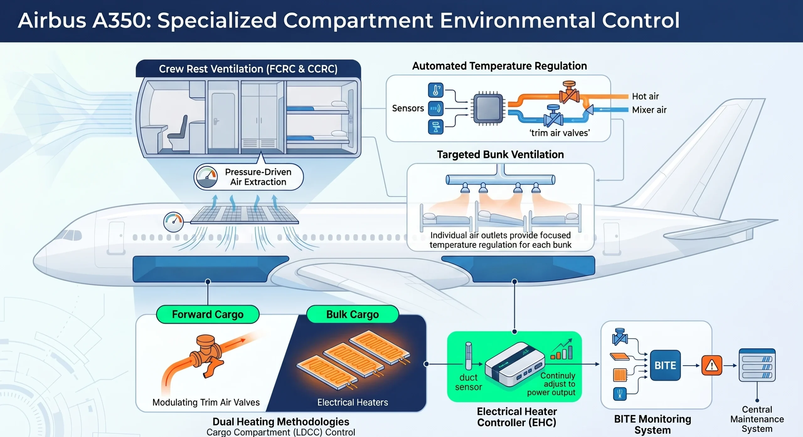
The crew rest ventilation system is a mission-critical environmental infrastructure designed to maintain the physiological readiness and operational focus of flight and cabin crew during extended long-haul sorties. By integrating localized climate zones into the aircraft’s broader environmental control loop, the system transitions from a passive air distribution network into a high-precision thermal management circuit. This ensures that isolated rest compartments provide a sustainable environment for recovery, meeting stringent certification standards for long-range operations.
The system’s modularity is defined by Manufacturer Serial Number (MSN) groups, allowing the environmental strategy to scale based on aircraft configuration:
- Combined FCRC/CCRC Configuration: MSNs such as 0657, 0691, 0715, and 0723 feature both a Flight Crew Rest Compartment (FCRC) and a Cabin Crew Rest Compartment (CCRC). Within these, bunk counts vary: MSNs 0691 and 0723 utilize a 6-bunk CCRC layout, whereas MSNs 0657 and 0715 are equipped with an 8-bunk CCRC architecture.
- FCRC-Only Configuration: MSNs including 0040, 0089, and 0582 are streamlined with only the Flight Crew Rest Compartment, maintaining flight deck operational support while simplifying the overall ducting requirements.
The physical airflow path is engineered around a pressure-differential release strategy:
- Supply Path: Conditioned air originates at the central mixer, routing through dedicated supply ducts to bunk-level ceiling outlets and individual “gasper” nozzles.
- FCRC Extraction Logic: Air is released through two specific grids: one located at foot level adjacent to the entrance door (exhausting to the cabin) and a second on the right side of the compartment releasing air behind the sidewall lining.
- CCRC Extraction Logic: Air is primarily removed via a connection to the commercial equipment ventilation system, supplemented by a pressure-driven grid release to the cabin.
- Passive Safety: This differential-driven exchange utilizes the high-pressure environment of the rest compartments relative to the cabin/lining areas, ensuring continuous air turnover without the failure modes associated with dedicated extraction fans.
This mechanical layout serves as the physical interface for the aircraft’s advanced digital control layer.
2. The Integrated Modular Avionics (IMA) Control Layer
The A350 architecture leverages the Integrated Modular Avionics (IMA) suite to host environmental applications, centralizing processing power within Core Processing Input/Output Modules (CPIOM). This shift from federated “black box” hardware to shared computational resources significantly reduces weight and enhances system-wide data integrity.
CPIOM H41 and H42 host the primary logic for rest area environmental control:
- Air Conditioning System (ACS) Application: Manages the high-level closed-loop thermal logic, processing temperature set-points and demand signals.
- Ventilation Control System (VCS) Application: Responsible for monitoring airflow distribution and regulating system-wide ventilation parameters.
A critical architectural distinction is the delegation of authority between the ACS application and the Air Systems Control Units (ASCU). While the ACS application identifies the thermal demand, it delegates the final “quantity calculation” for trim air to the ASCUs. This offloads high-frequency, real-time valve positioning tasks to localized controllers, ensuring that the IMA-level applications remain available for higher-level coordination and cross-system monitoring.
Data pathing is facilitated by Common Remote Data Concentrators (CRDCs) via the Avionics Full Duplex Switched Ethernet (AFDX) backbone.
| Component | Target Application | Communication Protocol | Functional Data Input |
| Duct Temp Sensor | ACS Application | ASCU Discrete / CAN | Measures air temperature arriving from the mixer. |
| Compartment Temp Sensor | ACS Application | CRDC to AFDX | Measures ambient temperature in FCRC/CCRC zones. |
| Additional Attendant Panel | ACS Application | CIDS to AFDX | Routes crew-selected temperature set-points. |
This digital processing layer translates electronic demands into physical adjustments through specialized sensor and valve hardware.
3. Sensor Integration and Feedback Loops
The maintenance of thermal stability within confined crew rest zones necessitates a dual-layered sensing strategy. By monitoring both the duct temperature (immediate supply) and the compartment temperature (ambient environment), the system provides the ACS application with the high-fidelity feedback required to prevent thermal oscillation.
The hardware specifications for these sensors ensure long-term stability:
- Duct Sensors: Located in the supply ducts, these typically utilize dual thermistor elements housed in stainless steel to monitor mixer output.
- Compartment/Extraction Sensors: Installed in the extraction paths (often between FR29 and FR30 in Zone 130 for forward sections), these utilize thermistor or platinum elements to provide ambient thermal data.
The system functions as an active closed-loop circuit. The ACS application processes the “delta” between the crew-selected set-point and the actual temperature. If the zone is too cold, the application sends a demand signal to the ASCUs to actuate the Trim Air Valve.
Trim Air Valve Mechanical Logic: Installed typically between FR44 and FR46 in Zone 130, the trim air valve is a butterfly-type modulating valve. It is driven by an electric stepper motor, which allows for extremely precise, incremental positioning. This mechanical precision is vital; it enables the system to bleed exact quantities of hot air from the trim air manifold into the cool mixer air, maintaining a stable temperature without the “overshoot” common in traditional solenoid-based systems.
This internal control logic is interfaced with the crew through several human-machine interface (HMI) points.
4. Operation, Control, and Indicating (OCI) Interfaces
Effective environmental management in high-stakes zones requires intuitive interfaces that provide both high-level monitoring and localized control.
The flight crew manages the system via the Control and Display System (CDS) “COND” page, located on the Main Instrument Panel. This interface provides situational awareness of ACS performance, allowing the crew to verify that the rest areas are receiving regulated ventilation and that the system is meeting the demanded thermal targets.
Localized control is managed through the Additional Attendant Panels (AAP). These panels allow crew members within the rest zones to adjust their environment without flight deck intervention. These local inputs are routed via the Cabin Intercommunication Data System (CIDS) to the ACS application, which then adjusts the trim air valve position to satisfy the local requirement.
Specific Control Locations:
- Main Instrument Panel: Centralized CDS for “COND” page monitoring.
- FCRC Entrance / Changing Area (Zone 130): Primary AAP for flight crew rest adjustments.
- CCRC Catwalk / Changing Area: Primary AAP for cabin crew rest adjustments.
These interfaces are supported by a robust underlying power and maintenance diagnostic infrastructure.
5. System Power Architecture and Maintenance Diagnostics
To ensure operational reliability on long-haul sorties, the ventilation and control hardware are integrated into the aircraft’s high-redundancy power grid.
The power distribution is categorized by load type:
- Primary Logic Power: The ASCUs are supplied by 115VAC main and emergency busbars, ensuring that control capability is maintained even during emergency electrical configurations.
- Actuator and Sensor Power: The trim air valves and sensors are supplied with 28VDC via the ASCUs or CRDCs, drawing from both normal and emergency busbars to ensure continuous feedback.
The Temperature Control System (TCS) utilizes a Built-In Test Equipment (BITE) architecture hosted in the CPIOMs. A master/slave relationship between BITE partitions prevents redundant failure reporting to the Centralized Maintenance System (CMS), ensuring that only validated, non-duplicative fault messages are logged.
Maintenance operators can initiate “Interactive Mode” on the ground to perform deep-system diagnostics:
- System Test: Validates the overall integrity of the temperature control and monitoring loops.
- Trim Air Valve Actuation Test: Exercises the stepper motor and butterfly valve to ensure smooth modulation and full-range movement.
- TCS Interfaces Test: Performs a comprehensive check of all temperature sensors and the digital data paths through the CRDCs.
- Temperature Control Override: A specialized maintenance function used for the high-temperature decontamination of the packs.
This integrated approach to avionics, power redundancy, and precise mechanical actuation establishes the A350’s crew rest ventilation as a benchmark in modern environmental control systems.